
 English
 русский
 Español
 عربى
عربى 简体中文
简体中文Multi Pin ECU Connector Layout Groups Signals and Power
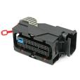
A multi pin ECU connector does more than carry a large number of wires. It sorts them. Inside one housing sit sensor signals, actuator drives, power feeds, and grounds, and the way those groups are placed decides how easy the harness is to build and how steady the signals stay on the road. Connectors in the over 60-pin range follow the same planning logic as smaller ones, only with more positions to organise.
Grouping pins by job
Signal pins carry small currents from sensors that measure temperature, pressure or position. Drive pins carry larger currents to injectors, relays and lamps. When the two types sit side by side, the switching current on a drive wire can add noise to a neighbouring sensor wire. Designers of a multi pin ECU connector therefore place sensor pins in one block, keep the heavier drive pins in another, and give the ground pins a row of their own.
Cavity size follows the job. Small cavities take fine signal terminals, and larger cavities take terminals for thicker power wire. A multi pin ECU connector with mixed cavity sizes lets the harness maker use light wire on the signal side and heavier wire on the drive side without splitting the circuit across two housings. That keeps the ECU wiring harness compact and the connection point in one place.
Each terminal is crimped for a stated wire range, so the terminal, the wire, and the seal are chosen together for every cavity. A harness engineer reading the pin table can see at once which cavities take fine wire and which take heavy wire, and the crimp tooling for each range can be set up before production starts.
Numbering supports the grouping. Positions carry moulded numbers or row letters, and the harness drawing uses the same references. A technician who reads pin 37 on the drawing finds pin 37 on the housing, and larger housings often add row and column marks so the eye does not have to count across sixty cavities.
Keying, locking and mating
Sixty or more terminals add up to a real mating force. Many housings use a lever or slide lock that draws the two halves together over a controlled stroke, so the fitter does not have to push hard on one edge.
Keying keeps the halves in the right orientation. Ribs and slots on the housing allow only one way of mating, and different key codes let two similar connectors sit in the same bay. In a vehicle, a multi pin ECU connector often stands near other ECU connectors of the same size, and colour or key coding keeps each cable with its own module.
A secondary lock adds a second check on the terminals. After the terminals are pushed into the housing, a wedge or a sliding cover closes behind them and holds each one at the correct depth. A multi pin ECU connector with this feature lets the line operator confirm the terminal positions in one glance before the harness goes to test.
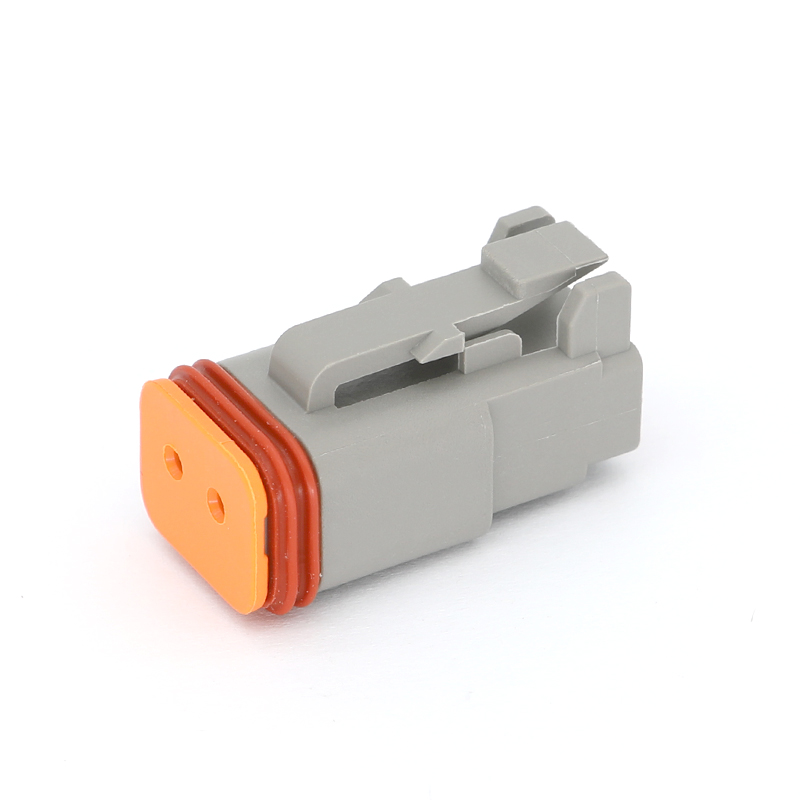
Sealing on a multi pin ECU connector follows the mounting position. An ECU inside the cabin can use an unsealed housing, while an ECU near the engine or under the floor uses a sealed one. In a sealed housing, every wire passes through a rubber seal, or a one-piece grommet, and unused cavities take plugs.
Planning the harness around the connector
A harness drawing usually starts at the connector, because the housing fixes the exit direction, the bundle diameter, and the bend radius. A rear cover guides the wires to one side, and an angled cover suits modules that sit close to a panel. The harness maker chooses the exit direction at the drawing stage so the bundle does not pull on the terminals after installation.
A short straight run behind the connector, before any bend, keeps the wires from loading the seal at the back of the housing. Tie-down points follow at regular spacing, and the ECU wiring harness continues along the body panel with clips at each turn.
Buyers developing a harness around a multi pin ECU connector can send the circuit list at the start. The pin groups, cavity sizes and wire ranges follow from that list, and the housing colour, key code and cover style can be adjusted for private label projects. A multi pin ECU connector matched to the circuit list on day one saves changes to the harness drawing later, and it lets the drawing office, the harness line and the vehicle maker read the same pin table. When the ECU wiring harness and the connector share one document, a multi pin ECU connector program moves from drawing to pilot build in fewer steps.